Product Description
Product Description
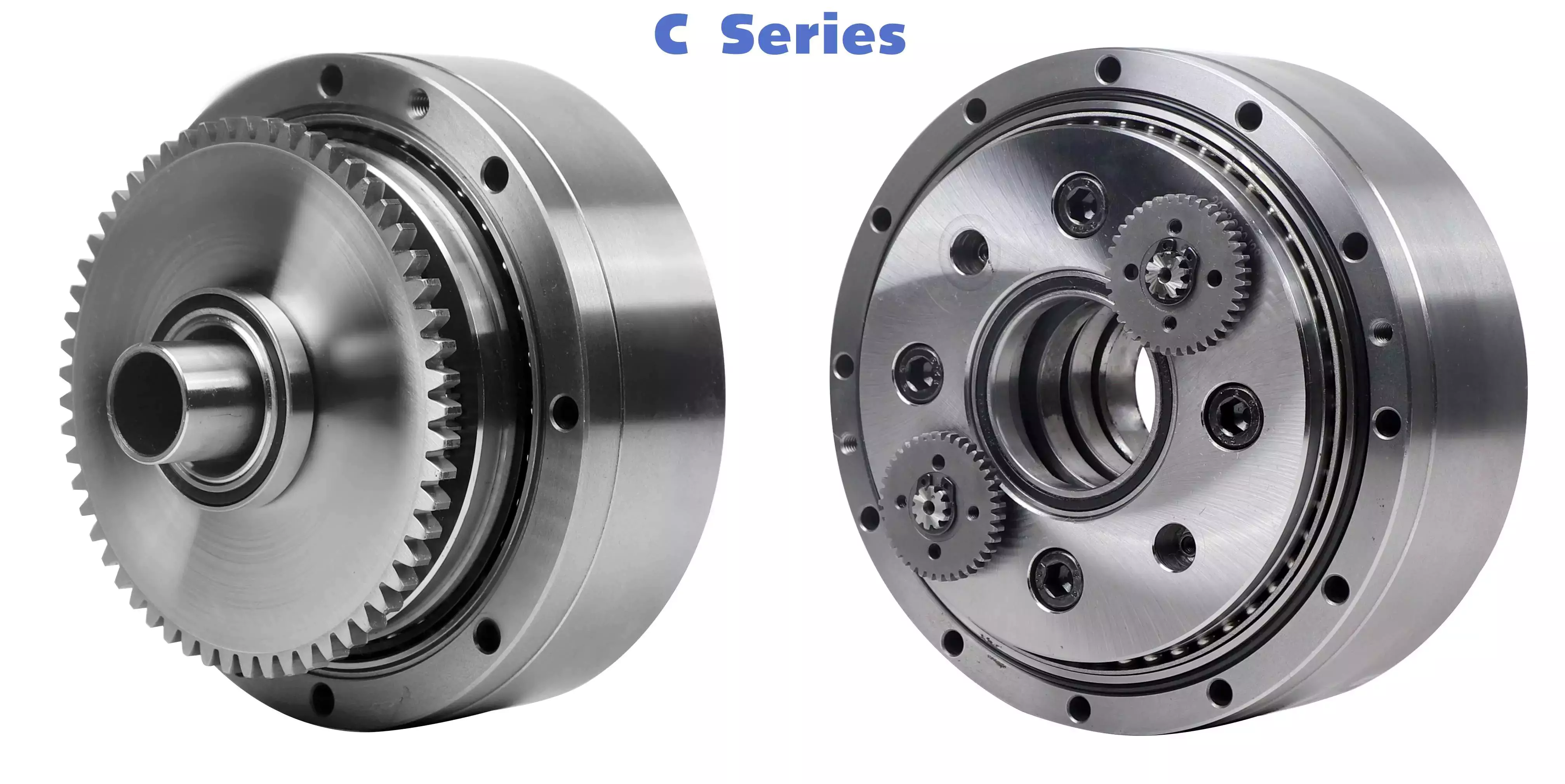
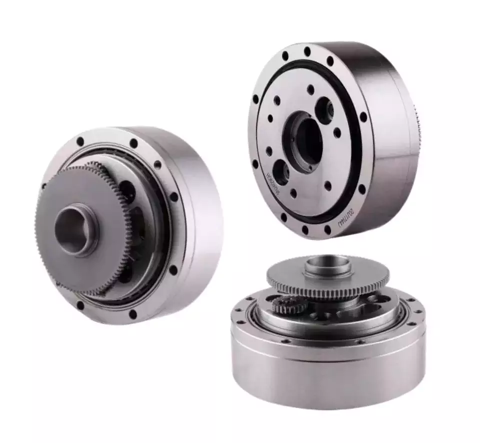
China Factory Wholesale high input speed planetary gearhead Gear Speed Reducer bevel gearbox
HangZhou Fubao Electromechanical Technology Co., Ltd. planetary gearhead Gear Speed Reducer bevel gearbox is a new generation of practical products independently developed by our company:
Low noise: less than 65db.
Low back clearance: up to 3 arc minutes in a CZPT and 5 arc minutes in a double stage.
High torque: higher than the standard planetary reducer torque.
High stability: high strength alloy steel, the whole gear after hardening treatment, not only the surface hard substitution.
High deceleration ratio: Modular design, planetary gearbox can be interlinked.
planetary gearhead Gear Speed Reducer bevel gearbox characteristic:
1.Planetary reducer manufacturer-Fubao Electromechanical Technology adopts an integrated planetary carrier and output shaft, which can provide better torsional rigidity. After precision machining, the gear set is not easy to eccentric, which can reduce interference, reduce wear and noise, and at the same time use a large The bearings are arranged with a wide span to distribute the load of the bearings, and once again strengthen the torque rigidity and radial load capacity of the planetary gearhead Gear Speed Reducer bevel gearbox. The output cover is made of aluminum alloy, which provides better heat dissipation capability for the product, so that the reducer produced by Fubao Electromechanical Technology can play an excellent role in the field of mechanical tools.
2.The planetary gear set is specially made of alloy steel. First, it undergoes quenching and tempering heat treatment to make the material hardness reach HRC30 degrees, and then undergoes nitriding surface treatment to HV860, so that the product has the characteristics of high surface hardness and high toughness in the center, and achieves the best product strength and service life. optimization.
3.The input shaft and the motor output shaft are connected by a bolted structure, with a round shaft seal design, and through dynamic balance analysis, it can ensure that there is no eccentric load at high speeds. After reducing unnecessary radial force, it can effectively Reduce the load on the motor side.
4.The material of the input cover/motor connection seat is made of aluminum alloy, which can provide better heat dissipation effect, and then provide good concentricity and verticality through professional lathe processing, so that the product can be stably combined with various motors, reducing the damage caused by insufficient precision. Unnecessary axial radial force makes the product have a longer life cycle.
Product Parameters
| WVB/WVBL series parameters | Model number | WVB042/WVBL50 | WVB60/WVBL70 | WVB/WVBL90 | WVB/WVBL120 | WVB142/WVBL155 | WVB180/WVBL205 | WVB220/WVBL235 |
| Rated output torque | 13-17Nm | 32-48Nm | 80-125Nm | 165-265Nm | 280-530Nm | 480-960Nm | 900-1360Nm | |
| Reduction ratio | L1: 3, 4, 5, 7, 10 | L2: 12, 15, 20, 25, 30, 35, 40, 50, 70, 100 | ||||||
| Planetary gear backlash | L1: P1≤3 P2≤5 L2: P1≤5 P2≤7 | |||||||
Detailed Photos
Product Details
Other products
Product Advantage
Compared with other reduction machines, planetary gear reduction machines have high rigidity, high precision (single stage can be achieved within 1 point), high transmission efficiency (single stage in 97-98%), high torque/volume ratio, lifetime maintenance free and other characteristics.
Because of these characteristics, planetary gear reducer is mostly installed on the stepper motor and servo motor, used to reduce speed, increase torque, matching inertia.
Company Profile
HangZhou Fubao Electromechanical Technology Co., Ltd. was established in 2008, the company has a complete precision reducer design, production capacity. Set R & D, manufacturing, assembly and sales, more in the field of gear manufacturing has more than 10 years of background, in the manufacturing equipment is equipped with Switzerland Riesenhahl gear grinding machine, domestic Qinchuan gear grinding machine, hamai gear hobbing machine and domestic Xihu (West Lake) Dis. gear hobbing machine, Japan Yasaki TLGmazak CNC lathe, CNC milling machine and other fully CNC equipment, In addition, it is equipped with other advanced measuring equipment such as Japanese TTI gear detector, 3 coordinate measurement, reducer backlash measurement instrument and so on. In a strong manufacturing capacity at the same time, can be stable, continuous manufacturing of high-quality precision reducer products.
The precision reducer produced by our company has the characteristics of high structural rigidity, small back backlash, precise transmission and so on. It is widely used in various industries. Companies adhering to the concept of let customers participate in manufacturing, and strive to provide customers with more personalized services. In the field of precision transmission has a unique achievements. It is our CZPT pursuit to make far-reaching contributions.
Factory Display
Q: Speed reducer grease replacement time
A: When sealing appropriate amount of grease and running reducer, the standard replacement time is 20000 hours according to the aging condition of the grease. In addition, when the grease is stained or used in the surrounding temperature condition (above 40ºC), please check the aging and fouling of the grease, and specify the replacement time.
Q: Delivery time
A: Fubao has 2000+ production base, daily output of 1000+ units, standard models within 7 days of delivery.
Q: Reducer selection
A: Fubao provides professional product selection guidance, with higher product matching degree, higher cost performance and higher utilization rate.
Q: Application range of reducer
A: Fubao has a professional research and development team, complete category design, can match any stepping motor, servo motor, more accurate matching.
| Application: | Motor, Machinery, Agricultural Machinery, Cobot |
|---|---|
| Hardness: | Hardened Tooth Surface |
| Installation: | Horizontal Type |
| Customization: |
Available
| Customized Request |
|---|
.shipping-cost-tm .tm-status-off{background: none;padding:0;color: #1470cc}
|
Shipping Cost:
Estimated freight per unit. |
about shipping cost and estimated delivery time. |
|---|
| Payment Method: |
|
|---|---|
|
Initial Payment Full Payment |
| Currency: | US$ |
|---|
| Return&refunds: | You can apply for a refund up to 30 days after receipt of the products. |
|---|

The Basics of a Cyclone Gearbox
Besides being compact, cycloidal speed reducers also offer low backlash and high ratios. Because of the small size of the drive, they are ideal for applications where space is a problem.
Involute gear tooth profile
Almost all gears use an involute gear tooth profile. This profile has a single curve, which means that the gear teeth do not have to be aligned closely with each other. This profile is smooth and can be manufactured easily.
Cycloid gears have a combination of epicycloid and hypocycloid curves. This makes them stronger than involute gear teeth. However, they can be more expensive to manufacture. They also have larger reduction ratios. They transmit more power than involute gears. Cycloid gears can be found in clocks.
When designing a gear, you need to consider several factors. Some of these include the number of teeth, the tooth angle and the lubrication type. Having a gear tooth that is not perfectly aligned can result in transmission error, noise and vibration.
The tooth profile of an involute gear is usually considered the best. Because of this, it is used in a wide variety of gears. Some of the most common applications for this profile are power transmission gears. However, this profile is not the best for every application.
Cycloid gears require more complex manufacturing processes than involute gear teeth. This can cause a larger tooth cost. Cycloid gears are used for less noisy applications.
Cycloid gears also transmit more power than involute gears. This can cause problems if the radii change tangentially. However, the shape is more simple than involute gears. Involute gears can handle centre sifts better.
Cycloid gears are less susceptible to transmission error. Cycloid gears have a convex surface, which makes them stronger than involute teeth. Cycloid gears also have a larger reduction ratio than involute gears. Cycloid teeth do not interfere with the mating teeth. However, they have a smaller number of teeth than involute teeth.
Rotation on the inside of the reference pitch circle of the pins
Whether a cycloidal gearbox is designed for stationary or rotating applications, the fundamental law of gearing must be observed: The ratio of angular velocities must be constant. This requires the rotation on the inside of the reference pitch circle of the pins to be constant. This is achieved through a series of cycloidal teeth, which act like tiny levers to transmit motion.
A cycloidal disc has N lobes which are rotated by three lobes per rotation around N pins. The number of lobes on a cycloidal disc is a significant factor in determining the transmission ratio.
A cycloidal disc is driven by an eccentric input shaft which is mounted to an eccentric bearing within an output shaft. As the input shaft rotates, the cycloidal disc moves around the pins of the pin disc.
The drive pin rotates at a 40 deg angle while the cycloidal disc rotates on the inside of the reference pitch circle of pins. As the drive pin rotates, it will slow the output motion. This means that the output shaft will complete only three revolutions with the input shaft, as opposed to nine revolutions with the input shaft.
The number of teeth on a cycloidal disc must be small compared to the number of surrounding pins. The disc must also be constructed with an eccentric radius. This will determine the size of the hole which will be required for the pin to fit between the pins.
When the input shaft is turned, the cycloidal disc will rotate on the inside of the reference pitch circle of roller pins. This will then transmit motion to the output shaft. The output shaft is supported by two bearings in an output housing. This design has low wear and torsional stiffness.
Transmission ratio
Choosing the right transmission ratio of cycloidal gearbox isn’t always easy. You might need to know the size of your gearbox before you can make an educated choice. You may also need to refer to the product catalog for guidance. For example, CZPT gearboxes have some unique ratios.
A cycloidal gear reducer is a compact and high-speed torque transmission device that reverses the direction of angular movement of the follower shaft. It consists of an eccentric cam positioned inside a cycloidal disc. Pin rollers on the follower shaft fit into matching holes in the cycloidal disc. In the process, the pins slide around the holes, in response to wobbling motion. The cycloidal disc is also capable of engaging the internal teeth of a ring-gear housing.
A cycloidal gear reducer can be used in a wide variety of applications, including industrial automation, robotics and power transmissions on boats and cranes. A cycloidal gear reducer is ideally suited for heavy duty applications with large payloads. They require specialized manufacturing processes, and are often used in equipment with precise output and high efficiency.
The cycloidal gear reducer is a relatively simple structure, but it does require some special tools. Cycloid gear reducers are also used to transmit torque, which is one of the reasons they are so popular in automation. Using a cycloidal gear reducer is a good choice for applications that require higher efficiency and lower backlash. It is also a good choice for applications where size is a concern. Cycloid gears are also a good choice for applications where high speed and high torque are required.
The transmission ratio of cycloidal gearbox is probably the most important function of a gearbox. You need to know the size of your gearbox and the type of gears it contains in order to make the right choice.
Vibration reduction
Considering the unique dynamics of a cycloidal gearbox, vibration reduction measures are required for a smooth operation. These measures can also help with the detection of faults.
A cycloidal gearbox is a gearbox with an eccentric bearing that rotates the center of the gears. It shares torque load with five outer rollers at any given time. It can be applied in many applications. It is a relatively inexpensive asset. However, if it fails, it can have significant economic impacts.
A typical input/output gearbox consists of a ring plate and two cranks mounted on the input shaft. The ring plate rotates when the input shaft rotates. There are two bearings on the output shaft.
The ring plate is a major noise source because it is not balanced. The cycloidal gear also produces noise when it meshes with the ring plate. This noise is generated by structural resonance. Several studies have been performed to solve this problem.
However, there is not much documented work on the condition monitoring of cycloidal gearboxes. In this article, we will introduce modern techniques for vibration diagnostics.
A cycloidal gearbox with a reduced reduction ratio has higher induced stresses in the cycloidal disc. In this case, the size of the output hole is larger and more material is removed from the cycloidal disc. This increase in the disc’s stresses leads to higher vibration amplitudes.
The load distribution along the width of the gear is an important design criterion. Using different gear profiles can help to optimize the transmission of torque. The contact stress of the cycloidal disc can also be investigated.
To determine the amplitude of the noise, the frequency of the gear mesh is multiplied by the shaft rate. If the RPM is relatively stable, the frequency can be used as a measure of magnitude. However, this is only accurate at close to failure.
Comparison with planetary gearboxes
Several differences exist between cycloidal gearboxes and planetary gearboxes. They are related to gear geometry and manufacturing processes. Among them, there are:
– The output shaft of a cycloidal gearbox has a larger torque than the input shaft. The rotational speed of the output shaft is lower than the input shaft.
– The cycloid gear disc rotates at variable velocity, while the planetary gear has a fixed speed. Consequently, the cycloid disc and output flange transmission accuracy is lower than that of the planetary gears.
– The cycloidal gearbox has a larger gripping area than the planetary gear. This is an advantage of the cycloidal gearbox in that it can handle larger loads.
– The cycloid profile has a significant impact on the quality of contact meshing between the tooth surfaces. The width of the contact ellipses increases by 90%. This is a result of the elimination of undercuts of the lobes. In this way, the contact force on the cycloid disc is decreased significantly.
– The cycloid drive has lower backlash and high torsional stiffness. This allows a cycloidal drive to be more stable against shock loads. The cycloid drive is also a compact design, which is ideally suited for applications with large transmission ratios.
– The output hub of the cycloid gearbox has movable pins and rollers. These components are attached to the ring gear in the outer gearbox. The output shaft is also turned by the planet carrier. The output hub of the cycloid system is composed of two parts: the ring gear and the output flange.
– The input shaft of a cycloidal gearbox is connected to a servomotor. The input shaft is a cylindrical element that is fixed to the planet carrier.

editor by CX 2023-10-22
